Engineering design challenge: Exploring a vehicle
Courtesy of: Engineers Nova Scotia
Goal
The goal of this activity is to become familiar with the parts of a vehicle. To see real life examples of sensors and learn to do basic tests (oil, tire pressure, fluid levels) on a vehicle. Learning the different parts of the dashboard introduces the concept of RPMs and velocity. There will be three cars near the classrooms set up for this activity. In the event of rain there will be large photographs of “under the hood” and a dashboard, tires will also be brought to do pressure tests on.
Materials you will need:
- Under the hood activity sheets
- Dashboard activity sheets
- Pressure gauges
- If a car is available in a safe environment, participants can take measure the tire pressure on the tires, look at the dashboard, and look under the hood. If a car is not available, print a photo of a dashboard and the diagram of under the hood.
Tire Pressure Activity: Instructions
-
Explain the Benefits of Correct Air Pressure:
Keeping the correct air pressure in your tires is as important as giving your engine a tune-up. In fact, the economic benefits may be even greater. With the right amount of air pressure, your tires wear longer, save fuel, enhance handling, and prevent accidents. Failure to maintain the correct air pressure can result in poor gas mileage, reduce tire life, and affect how the vehicle drives.
Because tires do so much without appearing to need attention, it's easy to forget about them. However, tires do lose pressure each day, through the process of permeation. In cool weather, a tire will typically lose one or two pounds of air per month. In warm weather, it's common for tires to lose air at an even higher rate. Tires are also often subjected to flexing and impacts that can diminish air pressure as well.
-
Explain “What is permeation?”
The process of permeation involves the diffusion of molecules, called the permeant, through a membrane or interface. Permeation works through diffusion; the permeant will move from high concentration to low concentration across the interface. A material can be semipermeable, with the presence of a semipermeable membrane. Only molecules or ions with certain properties will be able to diffuse across such a membrane.
-
Introduce the tire pressure gauge:
Hand a few gauges to the group to investigate. Ask them what they see on the gauge and identify the parts.
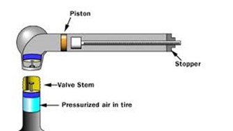
Inside the tube that makes up the body of the pressure gauge, there is a small, tight-sealing piston much like the piston inside a bicycle pump. The inside of the tube is polished smooth. The piston is made of soft rubber so it seals nicely against the tube, and the inside of the tube is lubricated with a light oil to improve the seal. In the picture, you can see that the piston is at one end of the tube and the stop is at the other. A spring runs the length of the tube between the piston and the stop, and this compressed spring pushes the piston toward the left-hand side of the tube.
The funny spherical thing on the left end of the gauge is hollow. The opening in the sphere is designed to engage a tire's valve stem. If you look in the opening, you will be able to see a rubber seal and a small fixed pin. The rubber seal presses against the lip of the valve stem to prevent air from leaking during the measurement, and the pin depresses the valve pin in the valve stem to let air flow into the gauge. The air will flow around the pin, through the hollow passage inside the sphere and into the piston chamber.
When the pressure gauge is applied to the valve stem of a tire, the pressurized air from the tire rushes in and pushes the piston toward the right. The distance the piston travels is relative to the pressure in the tire. The pressurized air is pushing the piston to the right, and the spring is pushing back. The gauge is designed to have some maximum pressure, and for the sake of example let's say it is 60 psi. The spring has been calibrated so that 60-psi air will move the piston to the far-right of the tube, while 30 psi moves the piston half-way along the tube, and so on. When you release the gauge from the valve stem, the flow of pressurized air stops and the spring immediately pushes the piston back to the left.
To allow you to read the pressure, there is a calibrated rod inside the tube:
 The spring is not shown in this figure, but the calibrated rod fits inside the spring. The calibrated rod rides on top of the piston, but the rod and the piston are not connected and there is a fairly tight fit between the rod and the stop. When the piston moves to the right, it pushes the calibrated rod. When the pressure is released, the piston moves back to the left but the rod stays in its maximum position to allow you to read the pressure.
 -
Now, have the participants take turns measuring the pressure on the tires (if tires or a car is available).
There are three simple steps involved in measuring a tire's pressure with a pressure gauge:
-
Get in a steady position to apply the pressure gauge to the valve stem.
-
Apply the gauge, forming a good seal between the gauge and the stem and releasing air from the tire into the gauge. Note how the pin inside the gauge presses against the valve pin inside the valve stem to release air from the tire.
-
Read the pressure from the gauge.
-
Dashboard Activity: Instructions
Ask participants to identify each:
-
Speedometer – A speedometer or a speed meter is a gauge that measures and displays the instantaneous speed of a vehicle. Speedometers for other vehicles have specific names and use other means of sensing speed. For a boat, this is a pit log. For an aircraft, this is an airspeed indicator.
There are two types of speedometers, eddy and electric. Here are explanations of both:
Eddy: When the car or motorcycle is in motion, a speedometer gear assembly turns a speedometer cable, which then turns the speedometer mechanism itself. A small permanent magnet affixed to the speedometer cable interacts with a small aluminum cup (called a speedcup) attached to the shaft of the pointer on the analogue speedometer instrument. As the magnet rotates near the cup, the changing magnetic field produces eddy currents in the cup, which themselves produce another magnetic field. The effect is that the magnet exerts a torque on the cup, "dragging" it, and thus the speedometer pointer, in the direction of its rotation with no mechanical connection between them.
The pointer shaft is held toward zero by a fine torsion spring. The torque on the cup increases with the speed of rotation of the magnet. Thus an increase in the speed of the car will twist the cup and speedometer pointer against the spring. The cup and pointer will turn until the torque of the eddy currents on the cup is balanced by the opposing torque of the spring, and then stop. Given the torque on the cup is proportional to the car's speed, and the spring's deflection is proportional to the torque, the angle of the pointer is also proportional to the speed, so that equally spaced markers on the dial can be used for gaps in speed. At a given speed the pointer will remain motionless and pointing to the appropriate number on the speedometer's dial.
The return spring is calibrated such that a given revolution speed of the cable corresponds to a specific speed indication on the speedometer. This calibration must take into account several factors, including ratios of the tailshaft gears that drive the flexible cable, the final drive ratio in the differential, and the diameter of the driven tires.
One of the key disadvantages of the eddy current speedometer is that it cannot show the vehicle speed when running in reverse gear since the cup would turn in the opposite direction - in this scenario the needle would be driven against its mechanical stop pin on the zero position.
Electric: In designs derived from earlier eddy-current models, a rotation sensor mounted in the transmission delivers a series of electronic pulses whose frequency corresponds to the (average) rotational speed of the driveshaft, and therefore the vehicle's speed, assuming the wheels have full traction. The sensor is typically a set of one or more magnets mounted on the output shaft or (in transaxles) differential crownwheel, or a toothed metal disk positioned between a magnet and a magnetic field sensor. As the part in question turns, the magnets or teeth pass beneath the sensor, each time producing a pulse in the sensor as they affect the strength of the magnetic field it is measuring.[1] Alternatively, in more recent designs, some manufactures rely on pulses coming from the ABS wheel sensors. Most modern electronic speedometers have the additional ability over the eddy current type to show the vehicle speed when moving in reverse gear.
A computer converts the pulses to a speed and displays this speed on an electronically controlled, analog-style needle or a digital display. Pulse information is also used for a variety of other purposes by the ECU or full-vehicle control system, e.g. triggering ABS or traction control, calculating average trip speed, or to increment the odometer in place of it being turned directly by the speedometer cable.
-
Engine Oil Temperature – There are basically two types of temperature gauges, electric and mechanical. Today's cars use electrical gauges but not too many years ago many used mechanical gauges that operated with a Bourdon Tube.
The Bourdon Tube: a thin metal - usually brass or copper - tube that is filled with an easily vaporized fluid, typically alcohol. It is sealed at both ends. At the gauge end it is formed into a circle or spiral with its end attached to the indicating needle by some form of linkage. The other end is fitted to a water-tight connector that is in direct contact with the coolant in the engine.
As the coolant warms up the alcohol in the Bourdon tube expands. The expansion transfers its force to the coiled end of the tube inside the gauge. As the coil or spiral unwinds it pulls the linkage on the needle, which in turn shows a temperature reading on the gauge face. The gauges are calibrated during the manufacturing stage and are not adjustable afterward.
Since the Bourdon Tube design is purely mechanical the gauge will continue to read some temperature level even after the engine is shut off. As the engine cools the gauge's needle will return to its rest position.
Bourdon Tube gauges aren't used anymore because of cost and convenience factors. The tubes are delicate and must be carefully routed from the dash to the appropriate fitting on the engine. The gauges themselves are far more expensive than electric or electronic gauges and if the tube is kinked or split the entire gauge assembly must be replaced.
Electric Temperature Gauges: Basically, an electric temperature gauge is a voltmeter. The scale on the gauge face is reading temperature but the instrument itself is reading voltage. The gauge itself is comprised of a bimetallic (two different metals fastened together) "hairpin" assembly. This assembly is attached to the needle.
The gauge requires an electric circuit and a sending unit in order to read temperature. The sending unit is a temperature-sensitive material that is part of a variable resistance, water-sealed unit that sits in the coolant stream in the engine. As the engine warms up the resistance in the sending unit is lowered gradually until the system reaches maximum heat. The sending unit is the "ground" portion of the circuit.
In the completed circuit the battery voltage passes from one side of the gauge, through the bimetallic spring and onward to the sending unit, which is grounded to the engine. When the engine is cold the resistance is high, so little current passes through the gauge. This small current doesn't heat up the bimetallic spring, so the gauge reads a low temperature. As the engine warms and the sending unit's resistance lowers more current passes through the gauge and the needle reads higher and higher because the bimetallic spring expands further.
Electric gauges can fail to read accurately because the sending units fatigue or rust over, or simply lose their connection to ground. The bimetallic spring can also fatigue over time, rendering the gauge inaccurate or inoperable.
-
Tachometer – A tachometer (revolution-counter, tach, rev-counter, RPM gauge) is an instrument measuring the rotation speed of a shaft or disk, as in a motor or other machine.[1] The device usually displays the revolutions per minute (RPM) on a calibrated analogue dial, but digital displays are increasingly common. The word comes from Greek ταχος (tachos "speed") and metron ("measure").
Tachometers or revolution counters on cars, aircraft, and other vehicles show the rate of rotation of the engine's crankshaft, and typically have markings indicating a safe range of rotation speeds. This can assist the driver in selecting appropriate throttle and gear settings for the driving conditions. Prolonged use at high speeds may cause inadequate lubrication, overheating (exceeding capability of the cooling system), exceeding speed capability of sub-parts of the engine (for example spring retracted valves) thus causing excessive wear or permanent damage or failure of engines. This is more applicable to manual transmissions than to automatics. On analogue tachometers, speeds above maximum safe operating speed are typically indicated by an area of the gauge marked in red, giving rise to the expression of "redlining" an engine — revving the engine up to the maximum safe limit. The red zone is superfluous on most modern cars, since their engines typically have a revolution limiter which electronically limits engine speed to prevent damage. Diesel engines with traditional mechanical injector systems have an integral governor which prevents over-speeding the engine, so the tachometers in vehicles and machinery fitted with such engines sometimes lack a redline.
-
Odometer – An odometer or odograph is an instrument that indicates distance traveled by a vehicle, such as a bicycle or automobile. The device may be electronic, mechanical, or a combination of the two. The word derives from the Greek words hodós ("path" or "gateway") and métron ("measure").
-
Fuel gauge – A fuel gauge (or gas gauge) is an instrument used to indicate the level of fuel contained in a tank. Commonly used in most motor vehicles, these may also be used for any tank including underground storage tanks.
As used in vehicles, the gauge consists of two parts:
The sensing unit: usually uses a float connected to a potentiometer, typically printed ink design in a modern automobile. As the tank empties, the float drops and slides a moving contact along the resistor, increasing its resistance.[2] In addition, when the resistance is at a certain point, it will also turn on a "low fuel" light on some vehicles.
The indicator: Meanwhile, the indicator unit (usually mounted on the dashboard) is measuring and displaying the amount of electrical current flowing through the sending unit. When the tank level is high and maximum current is flowing, the needle points to "F" indicating a full tank. When the tank is empty and the least current is flowing, the needle points to "E" indicating an empty tank.
The system can be fail-safe. If an electrical fault opens, the electrical circuit causes the indicator to show the tank as being empty (theoretically provoking the driver to refill the tank) rather than full (which would allow the driver to run out of fuel with no prior notification).
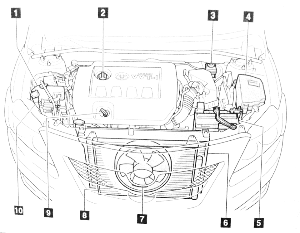
Under the Hood Activity: Instructions
Pass out the work sheets to the participants. Ask them if they can identify parts on the diagram or directly under the hood. As they identify them put the name on the part. When they identify the part give some information about it:
-
Engine coolant reservoir – Also known as antifreeze, engine coolant is used to achieve freezing-point depression for cold environments and also achieves boiling-point elevation ("anti-boil") to allow higher coolant temperature. The purpose of antifreeze is to prevent a rigid enclosure from bursting due to expansion when water freezes.
-
Level should be between Low and Full
-
-
Engine oil filler cap (Point out #9 at this time too) – A small, metal bar that shows you how much oil is left in the car. If it is near empty, refill with oil. If close to full, leave it alone.
-
It is best to keep the oil level near full.
-
Demonstrate how to check the oil. Have a few participants try it (all if interested and time allows).
-
-
Brake fluid reservoir – A translucent tank filled with fluid that is used to power the braking system of your car.
-
Level should be between MAX and MIN lines on the tank
-
-
Fuse box – Houses the fuses to run the electrical parts of the car.
-
Battery - A device that powers your car electronically. It is recharged when your car is running.
-
Radiator – A machine that cools the engine of the car, preventing overheating as a result. This is called a heat exchanger.
-
Electric cooling fan – Moves air into the car to cool the engine and other parts under the hood. During cold weather it won’t turn on to help the engine heat up faster.
-
Condenser – Another heat exchanger. While the radiator releases heat from the hot engine coolant passing through it, to the atmosphere, the condenser releases heat from the hot A/C system refrigerant passing through it, to the atmosphere.
-
Engine Oil Dipstick
-
Washer fluid tank – This holds the fluid used to clean your windshield with the wipers. In the winter antifreeze is added to this to keep it from freezing.